Fully-Loaded Geek

A site containing all things geeky

  • Projects
    • Red/Green LED Matrix 5x5x5
    • Automation Project
    • RC Pontoon Boat
  • Tutorials
    • How to fly Google Earth Flight Simulator with an Arduino joystick
    • Songs on an Arduino
  • Photography
  • About

Simple Hard Apple Cider

Posted by madjako77 on September 15, 2019
Posted in: Uncategorized. Leave a comment

Beginning of hard apple cider

Lately, I’ve been getting into brewing; beer, wine, hard apple cider, you name it! In this post, I’ll be talking about hard apple cider, but I may add more posts on other brews later. I’ve now made hard apple cider twice and have definitely enjoyed the results!

For those inexperienced with brewing hard apple cider, its pretty straight forward. Throw 1 tsp of yeast into a gallon of apple juice or apple cider in a sanitized 1-gal fermenter. Shake the mixture to increase the dissolved oxygen which helps build a healthy yeast colony. After a week, transfer (or “rack”) into another sanitized fermenter to allow the brew to clear.  For those interested in the terminology, the initial fermentation is “primary fermentation” and upon transferring is “secondary fermentation”. Generally, primary is when most of the alcohol is produced and secondary is when most of the clarity is achieved.

Once the brew is done fermenting (no longer bubbling), it is ready to be bottled. For bottling, “natural” carbonation is typically used (kegging is another article altogether). Natural carbonation is achieved by throwing a certain amount of sugar (usually 1oz per gal of white or brown sugar) into the brew. This restarts the fermentation causing more CO2 to be released. Once the sugar is mixed in, the result is put into bottles and those bottles are capped. You then have dry, carbonated cider ready to enjoy in a little over two weeks. However, aging the brew for a few more weeks produces a better result (some people age for months). Calculating alcohol by volume (ABV) requires the use of a hydrometer; you compare the density of the non-fermented liquid to the fermented liquid and multiply by 131.25. A typical apple juice has a density of 1.060 and typically finishes fermenting at 1.000; (1.060-1.000)*131.25 = 7.88%.

For sweet, non-carbonated apple cider, you can add more sugar before bottling and either add chemicals that prevent further fermentation or pasteurize to kill the yeast (otherwise way too much CO2 will be produced and you’ll potentially shatter your bottles). For sweet and carbonated hard apple cider (my preferred style) it gets more complicated; we’ll have to cover that in another article.

IOT Motion Sensor

Posted by madjako77 on January 3, 2017
Posted in: Uncategorized. Tagged: ESP, esp8266, Howto, ifttt, IOT, Micropython, Motion Sensor, NodeMCU, PIR, Python, smartthings, WebREPL. Leave a comment


Introduction

In this post, an Internet of Things (IOT) Motion Sensor will be created using an ESP8266 development module. For my specific setup, I will use a virtual SmartThings device and IFTTT to trigger a SmartThings light.

dsc_0232

Device Setup

I created a virtual device on my SmartThings hub to decouple the detection of motion from the device being activated. That way, the device being triggered can be redefined easily and conditions can be applied to the triggering. I used this post to setup a virtual device.

Once the virtual device (motion sensor device) was setup, I created two IFTTT recipes; one to turn on the motion sensor device and one to turn it off. The IF condition is the Maker Channel’s “Receive a web request” and the THAT condition is the SmartThings “Switch On” action.

Now to flash the MicroPython binary to the ESP8266 development board. I used the NodeMCU flasher tool with the binary from http://micropython.org/download. For the most part, I just connected the board, selected the binary, and then hit upload. After a short time, the board was working. I did find this guide useful though (you can use either esptool or NodeMCU flasher,  however, esptool failed for me).

Before proceeding, either download WebREPL or visit the hosted WebREPL. Once the binary is flashed and you have the WebREPL client running, the ESP hosts a WiFi network. Log into this WiFi network with micropythoN as the password. Then use the IP: “ws://192.168.4.1:8266/” with no quotes in WebREPL. This should connect and ask you to change the password and reset the device.

You’ll have to reconnect to the device’s WiFi network and reconnect in WebREPL. You now have a wireless python terminal that runs on the device.

Network Connectivity

Now, the device can be programmed without using the serial port, but only over the device’s WiFi network. To fix this, the device needs to be told on boot-up to connect to another network – allowing easier access as well as allowing the device to connect with services on the web.

The functionality to connect to a network can be added to the boot.py script. The general process for programming is to download the desired file (boot.py) using WebREPL (on the right). Then edit that program and re-upload. The starter boot.py has a few lines of code, but the following code is all you need.

import gc
import webrepl
import network

webrepl.start()
gc.collect()
gc.enable()

wlan = network.WLAN(network.STA_IF)

#Function that was on a getting started tutorial
def do_connect(ssid, password):
    wlan.active(True)
    if not wlan.isconnected():
        print('connecting to network...')
        wlan.connect(ssid, password)
        while not wlan.isconnected():
            pass
    print('network config:', wlan.ifconfig())

do_connect('SSID', 'PASSWORD')

The device can now be connected to with its IP address. The device’s WiFi network is still hosted and can be used even while its connected to another network. One issue is that you likely don’t know the address of the device on the new network. You can still connect via the hosted WiFi network and run wlan.ifconfig() in the WebREPL shell to find the address of the device. Another way is to setup a static IP based on the MAC address of the device. Unfortunately this process varies between wireless routers, so this part will have to be homework. Another way would be to use some service like IFTTT in order to be notified of your node’s bootup or possibly create two way communication with a web server (see my previous posts for a lower level look into sending messages to IFTTT).
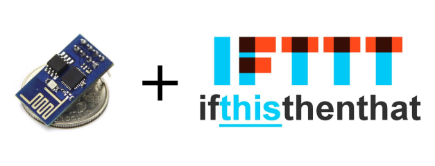
IFTTT integration

My previous posts explain some of the more nitty-gritty details of sending HTTP requests to IFTTT, however, these requests are greatly simplified with Micropython as sockets and web requests are handled at a much higher level. The following two functions allow the device to send messages to IFTTT:

import socket

#Simple function that handles sending a get request and printing the response
def http_get(site, port, reference, val1, val2, val3):
	address = socket.getaddrinfo(site, port)[0][-1]
	print('Connecting to ', site, '(', address, '):', port)
	s = socket.socket()

	s.connect(address)

	message = 'GET ' + reference + '?value1=' + str(val1) + '&value2=' + str(val2) + '&value3=' + str(val3) + ' HTTP/1.1\r\nHost: ' + site + '\r\n\r\n'
	print('Sending: ', message)
	s.send(message)
	print(s.recv(500))
	s.close()

#Simple function to handle sending the IFTTT get request to trigger an event
def ifttt_message(event, val1, val2, val3):
	http_get('maker.ifttt.com', 80, '/trigger/' + event + '/with/key/YOUR_IFTTT_KEY', val1, val2, val3)

#My bootup event that sends a notification to my phone with the LAN IP, Port, and WAN IP (currently not implemented) of the device
ifttt_message('node_bootup', wlan.ifconfig()[0], '8266', '?')

The functions are added after the other functions in the original boot.py and the last line of code is added toward the bottom of the script. This ensures that the functions have been defined before they are called (see below for full boot.py script).

Motion Sensor

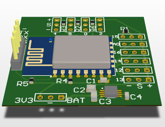
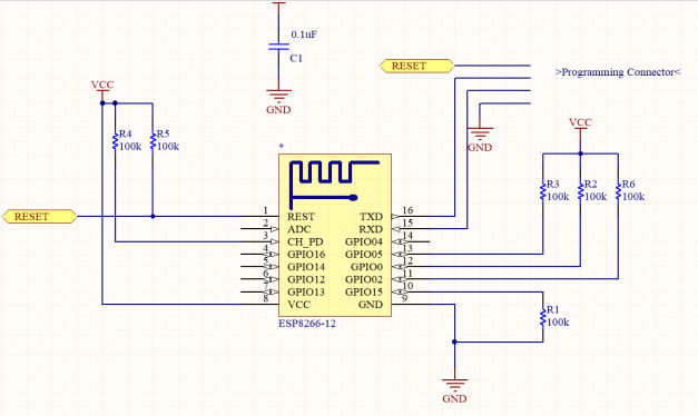
The last bit of functionality that needs to be added is the PIR motion sensor. This sensor has three pins: power, signal, and ground in that order. When powered, it sends a high signal when it has detected motion and a low signal when it has not. The sensitivity and signal hold time can be adjusted using the potentiometers on the side of the device. The signal can be read by nearly any GPIO on nearly any microprocessor. The ESP8266 with Micropython is no exception.

DSC_0355.jpg

PIR Motion Sensor

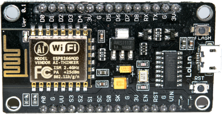
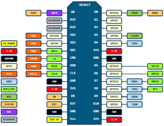
The motion sensor can be connected in the following way; VCC to 3.3V, signal to d1, and gnd to gnd. Here, pin d1 was chosen to be the digital input. Below is a good chart on the pinout of most dev kits. Here, D1 is GPIO5 or just 5 in Micropython.

esp8266-nodemcu-dev-kit-v2-pins

All that remains is to write some code that reads the motion sensor’s signal and responds (here I’ll be sending an IFTTT message). As I plan to have multiple devices with many different applications, the more general functionality is left in boot.py while application specific code is placed in main.py. Follow the previous link to see my implementation. The code has an interrupt that responds on rising edges which handles triggering motion. A loop is used to wait for motion timeout as well as send messages. I originally designed the whole program to operate in the interrupt function, however, it seems like the socket library must not be called within an interrupt. As calling socket.send() from either a timer interrupt or pin interrupt failed with errors such as “MemoryError” or simply exiting the interrupt routine.

Conclusion

When I walk into my bedroom, my SmartThings light comes on after a second or two. A short amount of time after I leave my bedroom, the light turns off. This comes at a price tag of about $5; $3 for the ESP dev board, $1-2 for the PIR sensor, and a few jumpers. Pretty good price compared to the $30+ motion sensors found online. However, one issue is that the reaction time is much slower than I would like. Speeding up the reaction time would be a nice future project.

Here is the boot.py I use with some added functionality I found useful along the way.

Useful Links

Programming an ESP8266 Dev board

Micropython Reference (ESP8266)

Micropython binaries

Cheap, easy to develop IOT devices

Posted by madjako77 on December 21, 2016
Posted in: Uncategorized. Leave a comment

dsc_0232

I recently received a few NodeMCU boards from Ebay. They came with a custom program loaded (not NodeMCU) and were a bit cryptic to figure out. Instead of messing with a custom program that I couldn’t find much documentation for, I tried flashing NodeMCU onto the board. I tried a few different methods and a few different versions and was unsuccessful. During my troubleshooting I ran across a Micropython implementation. I decided, what the heck, might as well give it a try. A few minutes later I was logged into the WebREPL server (more on this later) running python code on my ESP board. As I’m not fixated on using NodeMCU, I’m going to stick with what works easily — Micropython.

At this point you may be asking, “why the heck do I care about an ESP board with Micropython”, well, you might not. But I happen to care and here is why: with the combination of cheap WiFi enabled hardware and an easy to program platform, creating an IOT device is easier than ever. By adding a few custom functions that handle the typical tasks I want my devices to do, I can create wirelessly controlled devices with little effort.

After some messing around, I’ve found that Micropython is extremely stable and has enough functionality to be nearly identical to Python. Functionality is well implemented for writing to/reading from pins (analog and digital) as well as sending messages over WiFi. A handy feature is the WebREPL server hosted on the ESP which allows access to a Python shell running on the ESP. This is extremely handy, and if you generate a static IP for the ESP, it can be easily controlled anywhere in the world without much effort.

What next? Well, I have two applications in mind currently. First, I plan to make a motion sensor that will trigger my SmartThings lights. The device will be mounted in my room with a LiPo battery and a PIR sensor. Whenever motion goes off, the device, depending on the mode, will turn on the lights in the room. Second, I plan to create a WiFi enabled train controller. I’ve recently been given some American Flyer – O gauge model trains and want to move away from manually controlling the speed of the trains and the various switches to wireless control. I’ve already started both of these projects and should have the first one done soon.

Fractal Generator

Posted by madjako77 on September 26, 2016
Posted in: Uncategorized. Leave a comment

For just a bit of fun, I’ve been working on a repeating pattern generator which can generate fractal-like-structures. Currently the generator begins with one node, generates two children attached to the first, and then two children attached to those nodes, and on and on; it creates a tree like structure. The process looks like this:

4 levels generated using default settings

4 levels generated using default settings

This can be continued forever, however, I’ve created an input that limits the number of layers or levels of the tree. This generates quite interesting patterns like:

Interesting Rendering

Interesting Rendering

or

Interesting Rendering 2

Interesting Rendering 2

It can also be used to generate interesting animations such as this:

Simple Animation

Simple Animation

Implementation

The implementation for this is fairly straight forward if done recursively; in pseudo-code:

func processNode(inputNode)
    drawLine
    drawCircle
    if (inputNode.level < MaxLevel)
        child1 = new Node(child1Location, inputNode.level + 1)
        processNode(child1)
        child2 = new Node(child2Location, inputNode.level + 1)
        processNode(child2)
    endif
end

This code would execute fine, however, for large numbers of recursions, this will quickly fill up the available stack space and eventually crash the program. For this we can convert it to a more iterative approach. I chose to place all nodes in a queue as they are generated and to pull from the queue constantly. This provides an easy way to save the children nodes as well as removes the recursive nature.

Below is the core of the logic, you would add a first node to the queue at the beginning and then run processNodes continuously until all nodes are processed.

func processNodes()
    node = nodeQueue.dequeue()
    if (node.level < MaxLevel)
        DrawNode(node)
        children = GenerateChildren(node)
        nodeQueue.add(children)
    endif
end

Code Details

I originally chose javascript for portability reasons. I found javascript to be a pretty good language for this application, however, I wanted to try to make a faster program. I switched to WPF with C# to speed it up. However, the usual way of drawing things in WPF is to use FrameworkElements, which doesn’t work for large number of elements. Then I tried the DrawingVisual and DrawingContext which is the next best way to render images. This too was much too slow with large amounts of drawing calls. I considered Direct 2D but ultimately chose to draw directly to bitmaps because this seemed a little more straightforward.

I found a NuGet package called WriteableBitmapExtensions which adds a few very handy extensions to the WriteableBitmap class. I implemented the code close to the above pseudo-code. First, I executed the processing function on a timer interrupt. This wasn’t efficient enough, so I threw the processing into an infinite loop on a background thread, which uses the dispatcher to put any UI calls onto the UI thread. This resulted in much much better performance then Javascript, FrameworkElements, or DrawingVisuals implementations.

For more info on the performances: WriteableBitmap executes around 100x faster than when I used Javascript. Javascript performs about 10x better than DrawingVisuals. DrawingVisuals performs about 2x better than FrameworkElements. This makes a certain amount of sense since DrawingVisuals and FrameworkElements draw at a very high level with low optimizations.

TL;DR start here:

After finding a speedy way of drawing (with writable bitmaps in C# WPF), I moved onto putting the work into more than one background thread. This wasn’t too difficult, but required moving a lot of the global variables to local variables that are passed into other functions. The program uses nearly 100% of all my 8 CPUs on my desktop with around 95% of the program’s computations going to the drawing calls. I was able to render 2^26 nodes in only a minute or two (that’s over 67 million nodes).

Conclusion

This isn’t as good as I would expect with say Direct2D or another more optimized solution. However, this was a lot of fun and was a good way to practice optimization and multi-threading. I’ve found myself spending quite a while messing with the settings finding interesting patterns.

Source Code

I’ve included the source code below. As this is not a large project, I was willing to break some best practices to speed up development; very little “proper” design patterns were used. Feel free to use and modify the code.

Fractals.zip (Click link, look for download button on the top right)

Future?

If I work more on this, I’m would like to create an automated way to generate large numbers of frames. Something to the effect of having a start frame with certain settings, an end frame with certain settings, and an option for the number of in-between frames (n). The program would generate n frames and save them to a specified folder. Long animations could be created quickly and easily (the above animation took absolutely forever).

Another possible next step would be to use/make a more optimized way to draw shapes and lines as the draw calls do not seem to be as efficient as they could be (and they aren’t using the GPU).

NodeMCU

Posted by madjako77 on September 16, 2016
Posted in: Uncategorized. Tagged: ESP, esp8266, ifttt, IOT, NodeMCU. Leave a comment

While building the parts list for the ESP IOT breakout, I came across a seller for NodeMCU boards and I was surprised by their low cost. For about the same price as my proposed IOT system, the NodeMCU has a number of advantages. As a result, I’ve decided to change the direction of my project slightly. The major reason for this is the support and pre-built code for the platform. This will get my project off the ground much faster.

What is NodeMCU?

NodeMCU is an open source project that is built on top of an ESP8266. It runs a firmware with a LUA interpreter and has built-in libraries for GPIO, networking, etc. It is meant to be similar to Arduino programming and looks like it does a pretty good job of abstracting the nitty gritty details of WiFi connections.

Next Steps

I plan on ordering a few boards soon, which will most likely mean I’ll get them in about 6 weeks. After that, I’ll be testing them out. Stay tuned for a sub-project on getting a NodeMCU board integrated with IFTTT.

ESP IOT Breakout

Posted by madjako77 on June 8, 2016
Posted in: Uncategorized. Leave a comment

CircuitFinished.PNG

After only a few hours of work, I’ve completed the circuit and it looks great! The big blue thing is the standard ESP-12 module. To the left is the programming connector. Below the blue part is the 3.3V power regulator. All around the board are 3-pin connectors that are compatible with servos. The connectors are all GPIOs except the A0 connection which is only for the internal ADC.

Up next, I’ll order the boards and all the components. I intend to order the PCB through OSHPark, the ESP-12 module from Ebay, and the rest of the components from Mouser (at least the ones I don’t already have).

For anyone wanting to look at this board in CircuitMaker, I believe you can search ESP IOT Breakout and it should come up. Let me know if that doesn’t work in the comments or by using the contact page. I’ll put up a parts list soon!

ESP8266 IOT Circuit

Posted by madjako77 on June 7, 2016
Posted in: Uncategorized. Leave a comment

In my last post on the ESP8266 and IFTTT, I said that I would prefer keeping the ESP8266 decoupled from the overall system. This meant using the standard AT commands to control the default firmware. However, after a few attempts at sending AT commands and parsing the responses, I’ve given up that idea; using the AT commands is too annoying and slow.

Instead, I plan to go in the opposite direction completely. I’m going to make the system completely coupled to the ESP8266s. The plan is to design a circuit board with the ESP8266-12 module which comes in a small surface mount layout. The GPIOs will be broken out similar to 3-pin servo connections to facilitate easy connection of various devices. If I can keep the overall circuit below $10 including the ESP-12 module, this circuit will be a very nice development board for low-cost smart home devices.

Here’s a quick snapshot of the CircuitMaker schematic in development (very basic start):

CircuitStarted

The circuit still needs all of its connectors and the power regulator. As soon as I have the first version done, I’ll include a reference so that anyone can order these boards/fork the project.

Stay tuned for more updates on this project…

ESP8266 + IFTTT

Posted by madjako77 on January 31, 2016
Posted in: Uncategorized. 4 Comments

ESP+IFTTT

Introduction:

The first stage of creating my own smart electronics was getting the communication between the device and my SmartThings hub. I decided to use IFTTT for a number of reasons. IFTTT allows my circuit to control much more than just SmartThings, and it also does not require me to write a smart app. The best way to get a custom device to communicate with SmartThings is by using the maker channel in IFTTT. This allows any device capable of basic HTTP requests to trigger IFTTT events.

For my overall project, I intend to keep the communication device (ESP8266 here) decoupled from the actual system. This is partially so that I don’t have to deal with writing custom code on the ESP, but it is also so that I can swap the radio for another in the future. As a result, I’m using the default AT firmware and a separate MCU (just needs a UART peripheral that can operate at 9600 baud).

IFTTT Setup:

Setting up IFTTT is fairly simple. Just create an account, create a recipe using the Maker channel trigger and the desired action. For testing, this could be an email or IF notification.

Before any commands are sent to the ESP, it is good to know what format we need to use. IFTTT’s maker channel uses simple HTTP requests, and the HTTP GET request is the easiest to use. A minimal GET request is shown below.

GET /internalReference?value1={val1}&value2={val2}&value3={val3} HTTP/1.1

HOST: maker.ifttt.com

If you were to format this as a string, it would be:

“GET /internalReference?value1={val1}&value2={val2}&value3={val3} HTTP/1.1\r\nHOST: maker.ifttt.com\r\n\r\n”

Note: the extra “\r\n” at the end tells the serve that the message is done.

As you can see from the HTTP GET message, we have the ability to send back 3 data values which can be used in the maker channel. If you don’t want to use these values, you can leave them off (everything after and including the ‘?’).

Now that IFTTT is setup and we know our message format, we can begin interacting with the ESP.

Hardware Setup:

For this part of the project, I’m connecting the ESP8266 to an Arduino as a USB to Serial converter. I hooked up the ESP to the Arduino (with chip removed) as shown in the image below. It is advisable to use an external 3.3V regulator, however, when I used the Arduino, the on-board regulator worked fine for me.

ESP Hookup

AT commands:

To configure and use the ESP, we need to use the AT commands. All the AT commands can be found here.

The first thing we need to do is configure the ESP:

AT+CWMODE=3    // allows both client and host capabilities

AT+CIPMUX=1      // allows multiple connections

We can list the available APs:

AT+CWLAP

To connect:

AT+CWJAP=”SSID”,”PASSWORD”    // no spaces, quotes are required

To disconnect (quit)

AT+CWQAP

Once connected to our AP, we need to make a TCP/IP connection and send our data.

To make a TCP connection (no spaces, quotes required) we send:

AT+CIPSTART=CHANNEL,”TCP/UDP”,”ADDR/IP”,PORT

In our case we send:

AT+CIPSTART=0,”TCP”,”maker.ifttt.com”,80

After this point, you have a connection to maker.ifttt.com. This connection has a timeout, so it is best to have the next command ready.

Now we need to send our HTTP GET message. In general the message is:

AT+CIPSEND=CHANNEL,LENGTH

GET /internalReference?value1={val1}&value2={val2}&value3={val3} HTTP/1.1

HOST: maker.ifttt.com

Here, the string we defined earlier is very useful (that is as long as your serial terminal supports the escape characters \r\n, I use RealTerm). This allows us to send the entire command all at once and can be essentially dropped into a program:

“AT+CIPSEND=0,LENGTH\r\nGET /internalReference?value1={val1}&value2={val2}&value3={val3} HTTP/1.1\r\nHOST: maker.ifttt.com\r\n\r\n”

For example, triggering the “light_on” event through the maker channel:

AT+CIPSEND=0,91\r\nGET /trigger/light_on/with/key/YOUR_KEY_HERE?value1=1 HTTP/1.1\r\nHost: maker.ifttt.com\r\n\r\n

One note on the send message: I’ve found the most annoying part of these commands is calculating their length. The length is everything after the AT+CIPSEND=0,x including the \r\n and you count all characters (\r = 1, \n = 1). The above message should be accurate in its length.

Finally, its good practice to close the connection:

AT+CIPCLOSE=0

All together now:

AT+CWMODE=3

AT+CIPMUX=1

AT+CWJAP=”SSID”,”PASSWORD”

AT+CIPSTART=0,”TCP”,”maker.ifttt.com”,80

AT+CIPSEND=0,91\r\nGET /trigger/light_on/with/key/YOUR_KEY_HERE?value1=1 HTTP/1.1\r\nHost: maker.ifttt.com\r\n\r\n

AT+CIPCLOSE=0

After sending all these commands, you should get a response from the IFTTT server, stating that you successfully triggered the event and you should also have your action triggered.

Stay tuned for the next post about executing all these commands from a MCU connected to the ESP.

SmartThings!

Posted by madjako77 on January 6, 2016
Posted in: Uncategorized. Tagged: esp8266, ifttt, smartthings. Leave a comment

I’ve always been interested in home automation and IoT devices, and I’ve finally decided to get into the still growing world of smart devices. I got my hands on a SmartThings hub and have been brainstorming all the wonderful things I want to do with it. To start, I bought two GE Link Soft White bulbs, these bulbs were $14.97 from Home Depot, they linked to the SmartThings app with great ease and reacted swiftly to the smartphone app. I was able to create some routines that controlled these lights when I leave the house, and return. Overall I am very impressed with everything that the SmartThings system can do.

However, the overwhelming cost of smart devices has chilled my passion somewhat. At the time of this writing, just about every smart device on the market starts at $35 (except bulbs). At $35 a piece, even a small collection of devices becomes incredibly expensive. Those who are familiar with smart devices would likely be scolding me at this point, telling me that I should have done my research. In all fairness, I did know what I was getting into before I started and I still find it a good idea.

Knowing what I got myself into, I’ve begun collecting my resources and planning. I plan to create some WiFi enabled devices based on the ESP8266 chips that interface with IFTTT. For those who don’t know about IFTTT (If This Than That), IFTTT is a simple way to allow an event to perform an action. As an example, you could create a “recipe” that when the forecast predicts an overnight freeze, it will send you an email (see here). There is a way to send simple HTTP messages to IFTTT and have IFTTT trigger your SmartThings apps with the Maker Channel. The combination of IFTTT and the ESP8266 will create a simple solution for interfacing with my current and future SmartThings devices.

Stay tuned for my ESP+IFTTT project.

Upcoming Posts | I’ve been away

Posted by madjako77 on February 11, 2015
Posted in: Uncategorized. Leave a comment

For anyone who has seen my blog, they might realize that I haven’t posted in a while. I created this blog to show off some of my projects, but beyond that, it had no other purpose. As soon as I became busy, I lost the determination to keep posting about my projects.

I’ve now been involved with UNL’s Maker Club and have regained my passion for sharing my projects. But this time, I’m sharing them to teach others and excite them about “Making”. I have a few projects I’ve already completed and some exciting projects I will be working on.

As I need to gather some pictures and details, I won’t include any detailed projects in this post. However, I will give you a brief summary of posts you can expect soon.

  • Home-built quadcopter (how-to)
  • Cheap WiFi enabled circuits
  • DSLR timelapse circuit with Arduino
  • LED Strips controlled over XBees
  • Oculus Rift DK2 experiences
  • Game design (VR support)
  • Powerful ideas for embedded programming (Make coding easier/better for embedded C/Arduinos)

Stay tuned for project details!

Posts navigation

← Older Entries
  • Follow Fully-Loaded Geek on WordPress.com
  • Pages

    • About
    • Photography
    • Projects
      • Red/Green LED Matrix 5x5x5
      • Automation Project
      • RC Pontoon Boat
    • Tutorials
      • How to fly Google Earth Flight Simulator with an Arduino joystick
      • Songs on an Arduino
  • Recent Posts

    • Simple Hard Apple Cider
    • IOT Motion Sensor
    • Cheap, easy to develop IOT devices
    • Fractal Generator
    • NodeMCU
  • Most Viewed Pages

    • Simple Hard Apple Cider
    • IOT Motion Sensor
    • Cheap, easy to develop IOT devices
  • Search

Website Powered by WordPress.com.
Fully-Loaded Geek
Website Powered by WordPress.com.
Privacy & Cookies: This site uses cookies. By continuing to use this website, you agree to their use.
To find out more, including how to control cookies, see here: Cookie Policy
  • Subscribe Subscribed
    • Fully-Loaded Geek
    • Already have a WordPress.com account? Log in now.
    • Fully-Loaded Geek
    • Subscribe Subscribed
    • Sign up
    • Log in
    • Report this content
    • View site in Reader
    • Manage subscriptions
    • Collapse this bar
 

Loading Comments...